A manual transfer switch is a crucial component enabling safe power transfer between main and backup sources during outages. Simple to operate, it ensures reliable electrical system operation for homes and businesses.
1.1 What is a Manual Transfer Switch?
A manual transfer switch is an electrical device designed to safely transfer power between two sources, such as a primary utility supply and a backup generator. It is installed next to the main service panel and allows users to override the normal electrical service with power from a generator during outages. The switch ensures that only one power source is connected to the electrical system at a time, preventing dangerous backfeeding. It is a critical component for homes and businesses, providing a reliable way to maintain power continuity; The switch is user-friendly, requiring manual operation to switch between sources, and is essential for safety and system protection.
1.2 Importance of a Manual Transfer Switch in Electrical Systems
A manual transfer switch is essential for ensuring safety and continuity in electrical systems. It prevents dangerous backfeeding, which can harm utility workers and equipment. By enabling seamless power transfer from the main supply to a generator during outages, it maintains uninterrupted power for critical systems. This switch protects sensitive equipment from voltage fluctuations and surges. It is a cost-effective solution for backup power, reducing downtime and ensuring operational reliability. Additionally, it simplifies compliance with electrical codes and safety standards, making it a vital component for both residential and commercial electrical setups. Its role in preventing electrical hazards and ensuring system integrity cannot be overstated.
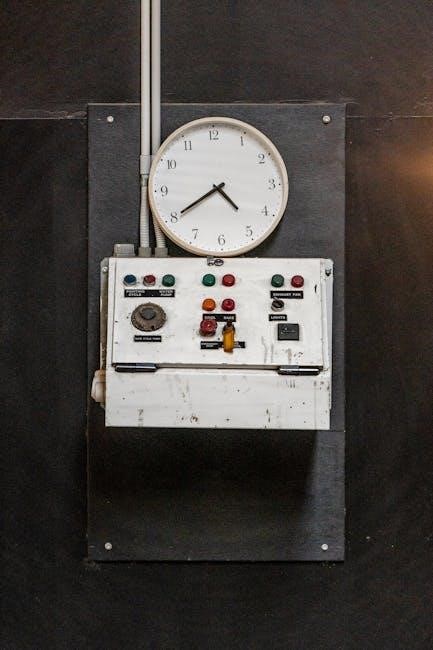
Key Components of a Manual Transfer Switch
A manual transfer switch comprises a switch mechanism, power source connections, circuit breakers or fuses, wiring, and an enclosure to safely manage power distribution.
2.1 The Switch Mechanism
The switch mechanism is the core component of a manual transfer switch, enabling manual switching between two power sources. It consists of a lever or handle that physically connects and disconnects the power sources. The mechanism ensures reliable operation during power outages by allowing users to safely transfer loads between the main power supply and a backup generator. Designed to handle high currents, the switch mechanism includes contacts and terminals for secure connections. Its simplicity and durability make it a critical part of ensuring uninterrupted power supply. Proper installation and maintenance are essential to guarantee smooth operation and prevent electrical hazards. The mechanism is typically rated for specific voltage and current levels, matching the system requirements. It is built to withstand frequent use and harsh environments, ensuring long-term reliability. Regular inspection of the switch mechanism is recommended to maintain optimal performance and safety. This component is fundamental for the overall functionality of the manual transfer switch, providing a secure and efficient way to manage power sources. By design, it prevents simultaneous connection of both power sources, eliminating the risk of backfeeding. The switch mechanism is a straightforward yet essential element in electrical systems, ensuring safe and reliable power transfer. Its robust construction and precise engineering make it a cornerstone of manual transfer switches, trusted in residential and commercial applications alike. The mechanism’s operation is intuitive, requiring minimal training for users to switch power sources effectively. It is a testament to electrical engineering, providing a practical solution for power management during outages. The switch mechanism’s reliability is unparalleled, making it an indispensable part of modern electrical infrastructure. Its importance cannot be overstated, as it directly impacts the safety and continuity of electrical systems. The mechanism’s durability ensures it remains functional even after years of service, making it a worthwhile investment for any electrical setup. By prioritizing safety and efficiency, the switch mechanism sets the standard for manual transfer switches worldwide. Its innovative design and proven performance have solidified its place as a vital component in electrical systems. The switch mechanism is more than just a part; it is the heart of the manual transfer switch, ensuring power is always available when needed. Its contribution to electrical safety and reliability is immeasurable, making it an essential element for homes and businesses alike. The mechanism’s ability to handle high currents and voltages ensures it can support even the most demanding electrical systems. Its versatility allows it to be used in various applications, from small residential setups to large industrial environments. The switch mechanism is a perfect blend of simplicity and functionality, offering users a dependable way to manage power sources. Its role in preventing electrical hazards cannot be overlooked, as it ensures safe switching practices. The mechanism’s design prioritizes user safety, reducing the risk of accidents during power transfers. Its construction materials are chosen for their durability and resistance to wear, ensuring long-lasting performance. The switch mechanism is a critical factor in the overall efficiency of the manual transfer switch, delivering consistent results in every operation. Its importance is reflected in its widespread use across different industries, where reliable power transfer is essential. The mechanism’s ability to adapt to varying electrical needs makes it a versatile solution for power management. Its reputation for reliability has made it a preferred choice for electrical professionals and homeowners. The switch mechanism is a shining example of engineering excellence, providing a practical and effective solution for power transfer needs. Its impact on electrical safety and efficiency is profound, ensuring systems remain operational during outages. The mechanism’s design is a masterclass in functionality, combining ease of use with robust performance. It is a testament to the ingenuity of electrical engineers, who have created a component that is both reliable and user-friendly. The switch mechanism continues to evolve, incorporating new technologies to enhance its performance and safety features. Its future looks promising, as it remains a vital part of electrical systems worldwide. The mechanism’s legacy is built on a foundation of quality and innovation, ensuring it remains a cornerstone of manual transfer switches for years to come. Its contributions to electrical safety and efficiency are unmatched, making it an indispensable component in modern electrical infrastructure. The switch mechanism is a true marvel of engineering, providing a practical and reliable solution for power management in any setting. Its importance extends beyond its function, as it plays a critical role in ensuring the safety and continuity of electrical systems. The mechanism’s ability to handle high currents and voltages with precision makes it a trusted component in both residential and industrial applications. Its durability and resistance to wear ensure it remains functional even in the most demanding environments. The switch mechanism is a perfect example of how simplicity can lead to exceptional performance, making it a cornerstone of manual transfer switches. Its role in preventing electrical hazards and ensuring safe power transfers is invaluable. The mechanism’s design is a perfect balance of form and function, offering users a reliable and efficient way to manage power sources. Its widespread adoption across industries is a testament to its effectiveness and reliability. The switch mechanism is an essential component that continues to play a vital role in electrical systems worldwide. Its impact on power management and safety is immeasurable, making it a fundamental part of modern electrical infrastructure. The mechanism’s legacy is built on a foundation of quality, innovation, and reliability, ensuring it remains indispensable for years to come.

2.2 Power Source Connections
Power source connections are vital in a manual transfer switch, enabling seamless integration of primary and backup power supplies. These connections ensure the switch can safely link to both the main electrical grid and a generator. Proper wiring is essential, with clear identification of live, neutral, and ground wires. The switch is designed to prevent simultaneous connection of both power sources, eliminating risks like backfeeding. Color-coded wires simplify installation, with black for hot wires, white for neutral, and copper for ground. Secure terminals and tight connections are critical to prevent electrical hazards. The switch must be rated to handle the combined load of both power sources. Following the wiring diagram ensures correct connections, maintaining safety and functionality. Regular inspection of these connections is recommended to prevent faults and ensure reliable power transfer. Proper installation guarantees safe and efficient operation during power outages. The connections must comply with electrical codes to avoid hazards and ensure system integrity.
2.3 Circuit Breakers or Fuses
Circuit breakers or fuses are essential components in a manual transfer switch, providing overcurrent protection for electrical systems. They safeguard against short circuits and overload conditions, ensuring safe operation. Proper sizing of circuit breakers or fuses is critical to handle the maximum current from both the main power source and the backup generator. These devices must be installed in line with the wiring diagram to ensure proper protection. Fuses act as sacrificial devices, while circuit breakers can be reset, offering convenience. Both must comply with electrical codes and ratings specified for the system. Regular inspection of these components is necessary to maintain reliability and safety. Improper installation or sizing can lead to system damage or fire hazards, making them a critical part of the transfer switch setup.
2.4 Wiring and Connectors
Wiring and connectors play a vital role in the functionality of a manual transfer switch. Properly sized wires ensure safe and efficient power transfer between sources. Connectors must be durable and compatible with the system’s voltage and current ratings. Terminal blocks or lugs are commonly used for secure connections, while wire nuts or solderless connectors provide reliable termination points. The wiring diagram specifies the correct routing and connections for all wires, ensuring compliance with electrical standards. Incorrect wiring can lead to system failure or safety hazards, so adherence to the diagram is crucial. Color-coded wires help simplify identification and organization during installation. Regular inspection of wiring and connectors is essential to prevent wear, corrosion, or loose connections, which can compromise system performance and safety. Proper installation techniques and materials are key to maintaining a reliable and secure electrical connection in the transfer switch setup.
2.5 Enclosure
The enclosure of a manual transfer switch serves as a protective housing for internal components, ensuring safety and durability. It shields the switch mechanism, wiring, and connectors from environmental factors like dust, moisture, and contaminants. Enclosures are typically made of durable materials such as metal, plastic, or fiberglass, with ratings like NEMA (National Electrical Manufacturers Association) indicating their level of protection. Proper enclosure selection is critical to prevent damage from harsh conditions and ensure reliable operation. A well-sealed enclosure also minimizes the risk of electrical hazards, such as arcing or short circuits. Regular inspection of the enclosure is recommended to maintain its integrity and protect the internal components of the transfer switch.

Understanding Wiring Diagrams
Wiring diagrams provide a visual guide for connecting power sources, loads, and switches. They use symbols and color coding to ensure correct and safe electrical connections;
3.1 Reading a Wiring Diagram
Reading a wiring diagram involves identifying components like switches, power sources, and loads. Start by locating the manual transfer switch, which acts as the control point between the main power and backup generator. Trace the wires to understand how they connect to the switch and other devices. Look for symbols representing circuit breakers, fuses, and connectors. Color coding helps differentiate between live, neutral, and ground wires. Follow the diagram step-by-step to ensure proper connections, starting from the power sources to the final loads. This systematic approach ensures safe and efficient installation or troubleshooting of the manual transfer switch system.
3.2 Common Symbols and Notations
Wiring diagrams use standardized symbols to represent components like switches, circuit breakers, and connectors. Common symbols include those for power sources, loads, and grounding points. Notations such as “L1” and “L2” denote live wires, while “N” stands for neutral and “G” for ground. Color coding is also used, with black for hot wires, white for neutral, and green or bare copper for ground. These symbols and notations help technicians interpret the diagram accurately. Understanding them is essential for safe and efficient installation or troubleshooting of a manual transfer switch system. Proper interpretation ensures all connections are made correctly, avoiding potential electrical hazards.
3.3 Color Coding of Wires
Wire color coding is essential for interpreting wiring diagrams accurately. Black wires typically represent hot (live) connections, while white wires signify neutral paths. Green or bare copper wires are reserved for grounding, ensuring safety. Red wires often indicate secondary live connections or phase-to-phase wiring in three-phase systems. Blue or yellow wires may denote auxiliary or control circuits. This standardized system helps technicians identify connections quickly and avoid errors. Consistency in color coding ensures compliance with electrical codes and enhances safety during installations or repairs. Always verify local regulations, as variations may exist. Properly following wire color codes is critical for reliable and hazard-free electrical system operation.
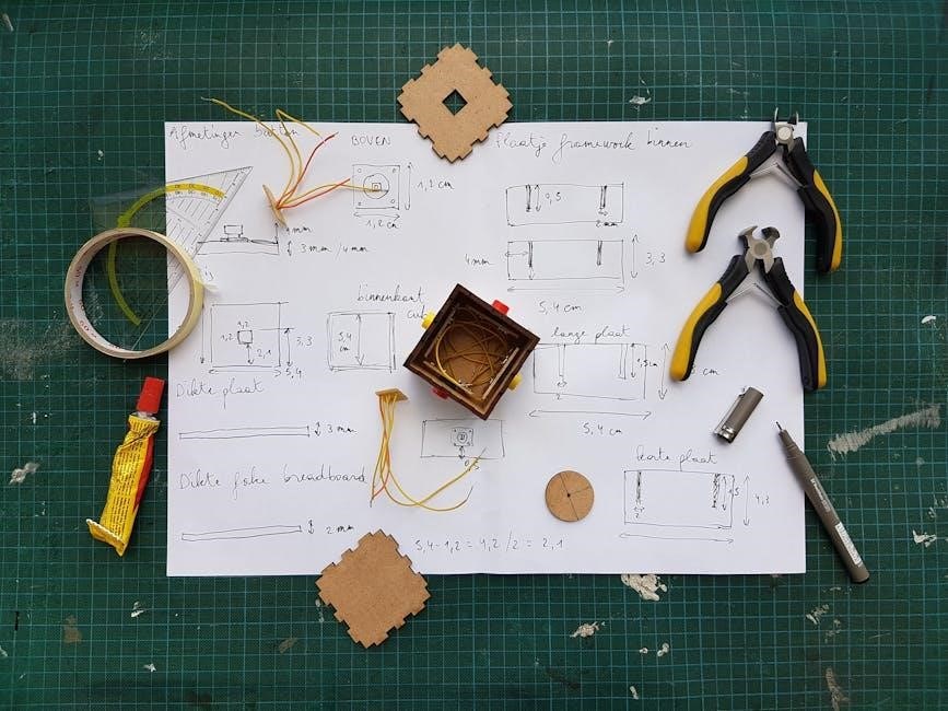
Installation Steps for a Manual Transfer Switch
Prepare the site, connect power sources, and link neutral and ground wires to the main panel. Test the system to ensure safe and proper functionality.
4.1 Preparing the Site
Before installing a manual transfer switch, ensure the site is safe and ready. Shut off the main power supply and verify this with a voltage tester. Select a location near the main electrical panel for easy access. Install the transfer switch enclosure securely, ensuring it is level and protected from environmental elements. Prepare the necessary wires, conduit, and connectors as per the wiring diagram. Verify that all local electrical codes are met, including proper wire bending spaces and conduit entries. Ground the enclosure correctly to ensure safety. Wear appropriate personal protective equipment (PPE) during preparation to prevent electrical hazards. A well-prepared site ensures a smooth and safe installation process.
4.2 Connecting Power Sources
Connect the ground and neutral wires from the transfer switch to the appropriate bus bars on the main electrical panel. Identify the main power source and backup generator, ensuring their connections align with the wiring diagram. Attach the wires to the transfer switch terminals, securing them with connectors. Verify polarity to avoid electrical hazards. Use a voltage tester to confirm power is off before connecting. Tighten all terminals firmly to ensure reliable connections. Follow local electrical codes and manufacturer instructions for proper installation. This step ensures safe and efficient power transfer between sources, preventing potential electrical risks and ensuring system functionality during outages.
4.3 Neutral and Ground Wire Connections
Connect the neutral wire from the transfer switch to the neutral bus bar in the main electrical panel. Similarly, attach the ground wire to the ground bus bar, ensuring a secure connection. Properly bonding these wires prevents electrical hazards and ensures safe system operation. Verify that the connections match the wiring diagram and comply with local electrical codes. Neutral and ground wires must not be interconnected incorrectly, as this can create safety risks. Use a voltage tester to confirm there is no power present before making connections. Tighten all terminals firmly to avoid loose connections, which can cause arcing or fires. This step is critical for maintaining electrical safety and system reliability during power transfers.
4.4 Circuit Connections
Connect the circuits from the manual transfer switch to the main electrical panel according to the wiring diagram. Ensure each circuit is securely attached to the correct terminal, matching the diagram’s specifications. Use a voltage tester to confirm there is no power present before making connections. Tighten all terminals firmly to prevent loose connections, which can cause arcing or fires. Double-check that the circuit wires are properly sized and rated for the load they will carry. Securely fasten the wires to avoid damage from movement or vibration. Verify that all connections align with local electrical codes and safety standards. Proper circuit connections are essential for reliable power distribution and system functionality during power transfers.
4.5 Testing the System

After completing the connections, test the manual transfer switch system to ensure proper functionality. Use a voltage tester to verify that there is no power present at the switch terminals. Simulate a power outage by disconnecting the main power source and activate the transfer switch to the backup generator. Check that the voltage levels match the wiring diagram specifications and that all circuits are receiving power. Ensure the system automatically switches back to the main power source when it is restored. Verify that all indicator lights and alarms function correctly. Test the circuit breakers or fuses to confirm they trip if an overload occurs. Perform additional tests as recommended by the manufacturer to ensure safe and reliable operation.
4.6 Final Inspection and Approval
After completing the installation, conduct a thorough final inspection to ensure all connections and components meet the wiring diagram specifications. Verify that the manual transfer switch is securely mounted and all wires are properly connected to the correct terminals. Check that the ground and neutral wires are correctly bonded to the main panel and that all circuit connections are secure. Ensure compliance with local electrical codes and that the system is approved by relevant authorities. Obtain final approval from a licensed electrician or inspector before operational use. This step ensures safety, reliability, and adherence to legal requirements, providing peace of mind for users.
Safety Precautions When Using a Manual Transfer Switch
Always wear personal protective equipment and ensure the system is grounded. Avoid overloading circuits and follow proper shutdown procedures during emergencies to prevent electrical hazards and injuries.
5.1 Electrical Hazard Warnings
When working with a manual transfer switch, understanding electrical hazards is critical. Live wires can cause severe shocks or electrocution, so ensure the power is off before any maintenance. Improper connections or overloaded circuits can lead to arcing, fires, or system damage. Always follow proper installation and safety guidelines to avoid such risks. Grounding and neutral connections must be correctly configured to prevent electrical shocks. Overloading the transfer switch can result in overheating, which may cause a fire hazard.Never bypass safety features or ignore warning signs, as this can lead to dangerous situations. Always prioritize caution when handling electrical systems to ensure safe operation.
5.2 Personal Protective Equipment
When working with a manual transfer switch, wearing appropriate personal protective equipment (PPE) is essential to ensure safety. This includes insulated gloves rated for high voltage, safety glasses, and a voltage-rated multimeter; These items protect against electrical shocks and arc flashes. Always verify that the equipment is in good condition before use. Additionally, ensure the work area is well-ventilated and free from flammable materials. Proper PPE helps prevent accidents and ensures compliance with electrical safety standards. Never attempt to handle live electrical components without proper protection, as this can lead to severe injury or death. Safety should always be the top priority when working with electrical systems.
5.3 Load Management
Effective load management is critical when using a manual transfer switch to ensure safe and efficient power distribution. Always prioritize essential circuits, such as lighting, refrigeration, and medical equipment, while avoiding overloading the system. Overloading can lead to tripped breakers or potential fire hazards. Refer to the wiring diagram to identify and label critical loads. Never connect high-power appliances like electric heaters or air conditioners without verifying the generator’s capacity. Proper load management prevents system failure and extends the lifespan of both the transfer switch and generator. Always follow the manufacturer’s guidelines for maximum load capacity to maintain safety and reliability during power outages.
5.4 Emergency Shutdown Procedures
In case of an emergency, immediately disconnect the power sources connected to the manual transfer switch. Move the switch to the “OFF” position to ensure no power flows through the system. Turn off all loads and wait for the system to stabilize before reconnecting. Always refer to the wiring diagram to identify the correct shutdown sequence. If a malfunction occurs, do not attempt repairs while the system is live. Instead, isolate the power sources and contact a certified electrician. Proper emergency shutdown procedures prevent accidents and protect both the transfer switch and connected equipment from damage. Always follow the manufacturer’s guidelines for safe operation during emergencies.
Legal and Compliance Considerations
Ensure compliance with local electrical codes and regulations when installing a manual transfer switch. Obtain necessary permits and follow inspection requirements to avoid legal issues.
6.1 Permits and Approvals
Installing a manual transfer switch requires obtaining proper permits and approvals from local authorities. These ensure compliance with electrical codes and safety standards. Before starting the installation, submit detailed plans, including wiring diagrams, to the relevant regulatory bodies. A permit guarantees that the work meets legal requirements and is inspected by certified professionals. Failure to obtain necessary approvals can result in fines, legal penalties, or even system disconnection. Always consult local building codes and electrical regulations to understand specific permit requirements for your jurisdiction. This step is critical to avoid legal complications and ensure a safe, compliant installation.
6.2 Compliance with Electrical Codes
Compliance with electrical codes is essential when installing a manual transfer switch. Local and national regulations, such as the National Electric Code (NEC) or International Electrotechnical Commission (IEC) standards, must be strictly followed. This ensures safety, proper functionality, and legal adherence. Wiring diagrams must align with these codes, detailing correct connections for power sources, neutral wires, and grounding systems. Non-compliance can lead to electrical hazards, system malfunctions, or legal penalties. Always verify local code requirements and consult certified professionals to guarantee adherence. Proper compliance ensures a safe and reliable electrical system, protecting both people and property from potential risks associated with improper installations.
6.3 Inspection Requirements
Regular inspections of a manual transfer switch are vital to ensure safe and efficient operation. Inspectors must verify that all connections, including ground and neutral wires, meet local electrical codes. They check for secure mounting, proper wire gauges, and adherence to wiring diagrams. Inspectors also ensure that the switch operates smoothly between power sources and that there are no signs of wear or damage. Compliance with codes like the NEC or IEC is crucial, and any deviations must be corrected promptly. Inspections should be conducted by certified professionals to guarantee system safety and reliability, preventing potential hazards and ensuring long-term functionality.

Troubleshooting Common Issues
Troubleshooting a manual transfer switch involves identifying faulty connections, diagnosing power issues, and resolving circuit problems. Use multimeters and wiring diagrams to pinpoint and repair issues effectively.
7.1 Identifying Faulty Connections
Identifying faulty connections in a manual transfer switch involves consulting the wiring diagram to locate potential issues. Use a multimeter to test for voltage and continuity, ensuring all wires are securely connected. Visually inspect connectors for signs of damage or corrosion, and verify that circuit breakers or fuses are functioning properly. Common issues include loose connections, overloaded circuits, or incorrect wire gauge. Always disconnect power before inspecting or repairing to avoid electrical hazards. If a connection fails testing, replace or tighten it as needed. After repairs, test the system to ensure proper operation and safety compliance. Regular maintenance can prevent future connection-related problems.
7.2 Diagnosing Power Problems
Diagnosing power problems in a manual transfer switch involves analyzing the wiring diagram to trace electrical flow. Use a multimeter to measure voltage at key points, ensuring it matches the expected values. Check for overloaded circuits, which can cause tripping or reduced power output. Verify that neutral and ground wires are correctly connected, as improper connections can lead to power imbalances. Inspect for loose or corroded terminals, which may disrupt the flow. Test each circuit individually to isolate faults. Consult the wiring diagram to identify potential bottlenecks or misconfigurations. After repairs, perform a full system test to confirm proper power distribution. Regular inspections can help prevent recurring issues and ensure reliable operation.
7.3 Tools and Techniques
Diagnosing and resolving issues with a manual transfer switch requires specific tools and techniques. A multimeter is essential for measuring voltage, current, and resistance, ensuring accurate troubleshooting. Use insulated screwdrivers and pliers to handle live wires safely. Refer to the wiring diagram to trace connections and identify potential fault points. Apply voltage testing at key terminals to confirm power availability. Check for loose or corroded connections using a torque wrench for secure tightening. Employ a circuit tester to verify proper wiring configurations. Regularly update your knowledge of electrical codes and best practices. Always prioritize safety, using personal protective equipment like gloves and safety glasses. By combining these tools and techniques, you can efficiently diagnose and repair power-related issues in a manual transfer switch system.
Maintenance and Upkeep
Regular inspection of connections and wiring ensures reliability. Clean dust and debris to prevent overheating. Check for loose terminals and replace worn components promptly. Schedule annual inspect by a licensed electrician to maintain optimal performance and safety.
8.1 Regular Inspection Schedule
A well-planned maintenance routine ensures the manual transfer switch operates efficiently. Inspect the switch monthly for signs of wear or damage. Check all connections and wiring for tightness and integrity. Look for corrosion or oxidation, which can disrupt power transfer. Test the switch mechanism to ensure smooth operation between power sources. Verify that the ground and neutral wires are securely connected to the main panel. Schedule a professional inspection annually to identify and address potential issues before they cause system failures. Regular cleaning of the enclosure and internal components prevents dust buildup, which can lead to overheating. Keep records of all inspections and maintenance activities for future reference.
8.2 Replacing Worn Components
Replacing worn components in a manual transfer switch is essential for maintaining reliable power transfer. Start by identifying worn parts using the wiring diagram. Ensure the power is off and discharge any capacitors. Use appropriate tools like screwdrivers, pliers, and a multimeter. Obtain compatible replacement parts and follow the diagram for correct installation. After replacement, test the system by simulating a power outage to ensure proper function. Regular inspections can prevent major issues, allowing proactive replacement of worn components. Always follow safety guidelines and consult additional resources if needed to ensure the switch operates safely and efficiently.
8.3 Best Practices for Longevity
Adhering to best practices ensures the longevity and reliability of a manual transfer switch. Regularly inspect the switch and its wiring, referencing the wiring diagram for accuracy. Always use appropriate tools and follow safety protocols when performing maintenance. Avoid overloading the system, as this can cause premature wear. Ensure all connections are clean and securely fastened to prevent electrical issues. Consider installing surge protectors to safeguard against voltage spikes. Test the switch periodically under load to confirm proper operation. Keep the surrounding area clean and dry to prevent dust buildup. Documenting maintenance activities helps track the system’s condition and ensures future reliability. By following these practices, you can extend the lifespan and maintain optimal performance of the manual transfer switch.

